Unveiling Interfaces and Structures: Cryogenic Laser Ablation and Plasma Focused Ion Beam Techniques for Complex and Beam-Sensitive Systems
Principles and Advanced Techniques
Principles and Advanced Techniques of Cryo-Laser PFIB for Battery Cross-Sectioning
Prototype Cryo-Laser PFIB Platform
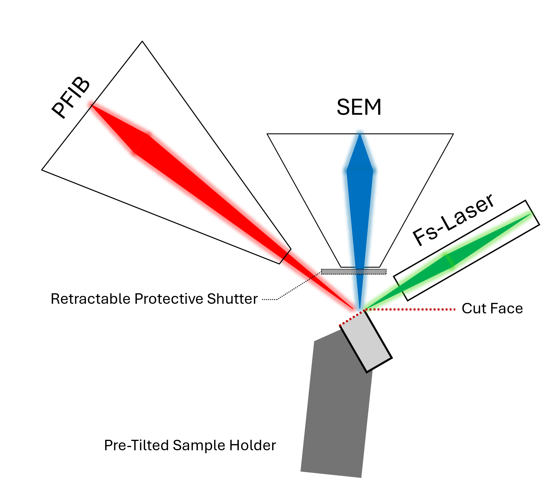
We developed the cryo-Laser PFIB workflow for coin cells on a Thermo Fisher Scientific Helios G3 Xe+ PFIB in 2019, which was modified to include an in-situ femtosecond UPL that could be used coincidently with the PFIB and SEM. As shown in Figure 2.1 , the electron column is vertical, the PFIB column is on the left (normal incidence at 52°), and the UPL objective lens is located on the right (normal incidence at -60°). To protect the SEM pole piece from UPL ablation debris, a rapid automated shutter was inserted during laser patterning. For room-temperature and standard workflows (Figure 2.1), commercially available pre-tilted holders enable cross-sectioning with the UPL at normal incidence as the typical stage tilt range (-10° to 60°) cannot reach normal incidence to the UPL with a sample mounted at 0°.

Figure 2.1:Schematic of pre-tilted sample holder for standard, room-temperture PFIB with integrated UPL work flows.
The integrated UPL has a wide parameter space and enables tunable features, including pulse energy, polarization, wavelength, and repetition rate. Using second harmonic generation, the UPL could operate at 1030 nm or 515 nm, with fast pulse durations (< 300 fs), broad pulse energy ranges (nJ to 59.817 J for 1030 nm and 37.489 J for 515 nm), and adjustable repetition rates (1 to 60 kHz). By changing the pulse energy and repetition rate, it is possible to tune the average power; in this case, reducing the repetition rate minimized the thermal load to the frozen sample. For example, fs-laser ablation of thermally sensitive samples (e.g., polymers) are likely to incur thermal damage when processed at higher repetition rates Ravi‐Kumar et al., 2019. A motorized objective lens was positioned inside of the chamber, allowing us to change the objective position (typically +/- 1 mm) to focus both laser wavelengths at the eucentric position. To further expand the parameter space, waveplates were added to make it possible to adjust the beam polarization to vertical (P), horizontal (S), or circular.
Laser Patterning and Automation for 2D-area and 3D-volume
For ease of use, the patterning engine for the integrated UPL (e.g., shape, size, pitch, and scan type) was set to closely mimic the original SEM-PFIB system’s patterning to create cross-sections and other pattern types, including circles, or custom pattern types (bitmap, streamfiles). A fast-scanning mirror (FSM) provides laser pattern control by steering the position of the UPL spot in a defined pattern. To further mitigate damage and precision patterning, the UPL “fine mode” patterning allows the user to tune the pulses-per-pixel (PPP) setting, precisely controlling the number of laser pulses used on each pixel in the pattern. For fragile materials, fine-mode patterning supports deterministic delivery of pulses with high precision, allowing only 1 PPP or few PPP in critical ROI. For less fragile materials that require higher throughput or very hard materials (e.g., stainless steel), it is also possible to use “coarse mode” patterning, which minimizes delay times between patterning loops (less precise steering of FSM) and sets a dwell time (ms) at the chosen repetition rate for each pixel rather than a defined PPP.
The Laser PFIB platform supports automated laser routines, where automated laser patterning can be performed in addition to traditionally automated SEM-PFIB and analytical routines. For example, combinations of UPL ablation, PFIB milling and/or imaging, SEM imaging, energy dispersive X-ray spectroscopy (EDS), and electron backscatter diffraction (EBSD) steps can be built into autonomous workflows. For example, 2D areas can be prepared by UPL/PFIB cross-sectioning/polishing and then imaged/analyzed via SEM/EDS/EBSD; alternatively, for 3D characterization, 2D areas can be prepared by serial sectioning, where defined slices are removed by UPL or PFIB and imaged/analyzed at each slice with SEM and/or EDS/EBSD to be reconstructed into a 3D volume. In this work, we will discuss automated UPL and SEM serial sectioning, where defined slices were removed by UPL ablation and SEM images were collected at each slice, which were reconstructed into a 3D volume. We automated this process to allow for the collection of serial section data (with laser only, PFIB only, or combination of both), by performing stage moves dependent on desired step size (slice thickness). While we used stage positioning to define the laser slice thickness, adjusting the FSM would have enabled similar control over slice placement.
Cryogenic Stage Integration
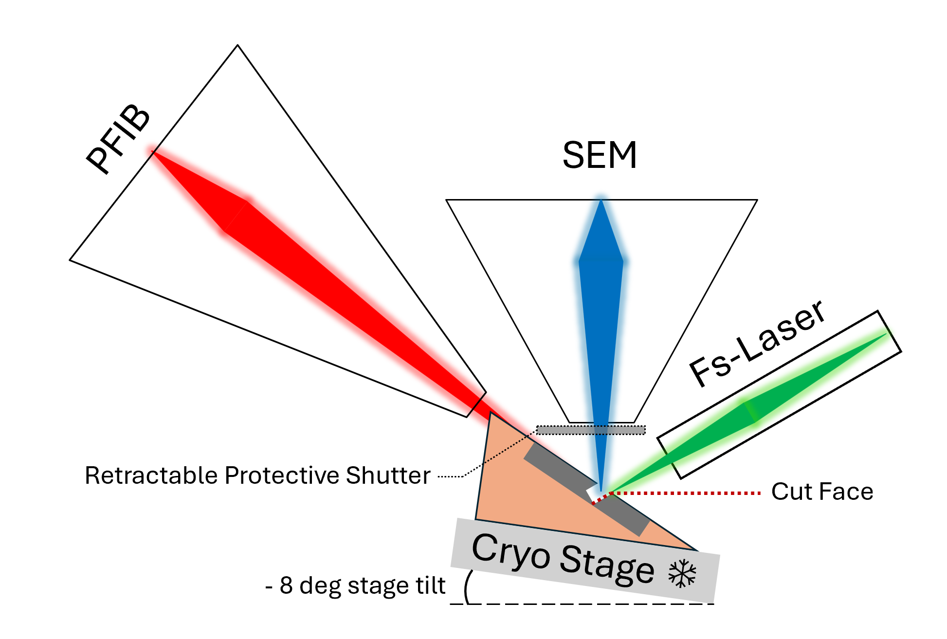
The assembled and prepared Li-metal coin cell batteries in half-cell form (CR2032, 20 mm diameter, 3.2 mm thick) Zhang et al., 2020Frisco et al., 2017 were mounted to custom copper pre-tilted holders designed for the diameter and thickness of the coin cells (SI). The custom machined holders were optimized to enable the largest pre-tilt angle (as close to normal incidence to the UPL as possible) while being able to access near-center ROIs on the coin cells. In preliminary efforts, we tested -21° to -26° pre-tilt angles, demonstrating that the largest holder pre-tilt angle possible for use on a Quorum cryo-stage that was still able to access ROIs at the edge and center of the coin cells was -26° at a stage tilt of -8°, which is at oblique incidence to the laser (-34° total pre-tilt). A -50° pre-tilted holder would have been necessary to achieve normal incidence at the maximum -10° stage tilt, but such a pre-tilt would have collided with the PFIB pole piece and laser protective shutter. A schematic of the pre-tilted coin cell holder in position for UPL ablation is shown in Figure 2.2 below.

Figure 2.2:Schematic of a coin cell in the custom pre-tilted coin cell holder at the stage position for UPL ablation. The oblique cross-section face is marked as “cut face”.
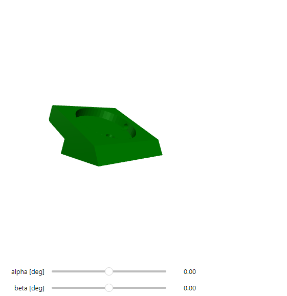
To improve overall performance, we made four additional modifications to the custom holder: (1) to monitor the local sample temperature, we added a platinum resistance temperature detector, (2) to firmly secure the sample and ground the cathode without increasing load on the holder, we added countersunk screws < 1 mm from the edge the sample, (3) to provide electrical isolation and prevent cell shorting, we added a layer of polyimide tape along the bottom of the recessed area of the sample mount to prevent cells from shorting to the holder, and (4) to ensure easier coin-cell mounting we machined the holder to the diameter and thickness of the coin cells. A 3D CAD model of the latest holder design iteration is shown in Figure 2.3 below.
We then optimized the sample cooling process to mitigate sample damage. Once prepared, the coin cells were stored in a 0°C freezer. In our first attempts, samples were mounted to the holder and then plunge frozen in liquid nitrogen (LN2). The frozen sample and holder were then transferred in air to a Quorum Cryo-stage; however, the fast freezing process induced thermal shock and delamination of the interfaces we wanted to preserve. In later attempts, we used a Styrofoam insulating container to make an LN2 bath, inside of which we placed two nested Pyrex beakers to slow the heat transfer from the LN2 bath. The coin cell sample was placed in the inner beaker for ~30 minutes and then moved directly into the LN2 bath, mitigating the possibility of thermal shock and delamination. While the samples were being cooled, the holder was mounted to the Quorum cryo-stage and cooled to at least -150°C. The Laser PFIB was vented and the cell was quickly mounted to the pre-cooled holder on the cryo-stage.
Stage tilt and rotation were limited by the stage tilt limits (-10° to +60°) and design of the Quorum cryo-stage, which prevented 360° stage rotation due to the connections of the cryo-stage tubing. The constraints incurred by lack of rotation of the Quorum cryo-stage and geometric considerations of the SEM/PFIB pole piece and protective laser shutter ensured that only ROIs near the center and top edge of the coin cell were accessible and restricted sample motion for advanced workflows (e.g., EBSD, EDS, and additional PFIB polishing).
- Ravi‐Kumar, S., Lies, B., Zhang, X., Lyu, H., & Qin, H. (2019). Laser ablation of polymers: a review. Polymer International, 68(8), 1391–1401. 10.1002/pi.5834
- Zhang, Y., Zuo, T.-T., Popovic, J., Lim, K., Yin, Y.-X., Maier, J., & Guo, Y.-G. (2020). Towards better Li metal anodes: Challenges and strategies. Materials Today, 33, 56–74. 10.1016/j.mattod.2019.09.018
- Frisco, S., Liu, D. X., Kumar, A., Whitacre, J. F., Love, C. T., Swider-Lyons, K. E., & Litster, S. (2017). Internal Morphologies of Cycled Li-Metal Electrodes Investigated by Nano-Scale Resolution X-ray Computed Tomography. ACS Applied Materials & Interfaces, 9(22), 18748–18757. 10.1021/acsami.7b03003


