Unveiling Interfaces and Structures: Cryogenic Laser Ablation and Plasma Focused Ion Beam Techniques for Complex and Beam-Sensitive Systems
Cross-Section Optimization
Optimized Cross-Section Preparation with Cryogenic Laser Ablation and Plasma Focused Ion Beam
Influence of Laser Parameters
Laser wavelength and polarization can influence the cross-section surface, therefore these parameters were investigated to develop an optimized cross-section workflow. In some ways, selecting the UPL wavelength and/or polarization is similar to selecting the ion species in a FIB/PFIB; one set of parameters may be more beneficial for a specific material or application. For each sample, the goal of the tuning process is to mitigate LIPSS or roughness on a UPL-ablated surface, which can appear on most classes of materials but tend to be most obvious on semiconductors and metals. LIPSS tend to appear as ripple-like features that are classified based on the pattern periodicity () of the structures: low-spatial frequency LIPSS (LSFL, ≈ laser wavelength), which usually occur perpendicular to the incident laser polarization, and high-spatial frequency LIPSS (HSFL, < laser wavelength), which can be aligned perpendicular or parallel to the incident laser. In cases where some features of interest are smaller than the spatial periodicity of LIPSS, those features could be masked; however, since LIPSS are only apparent on the surface of some materials, it can be useful for identifying LIPSS-vulnerable materials (e.g., metals, semiconductors) embedded within LIPSS-invulnerable materials (e.g., nonmetals).
To showcase the importance of wavelength tuning, we contrasted identically prepared coin cell samples polished using 515 nm UPL and 1030 nm UPL, respectively. Figure 3.1 (a) shows the ROI of the coin cell intermediate-polished using 515 nm UPL, where LSFL (average ≈ 400 nm) are primarily observed on the stainless-steel casing, Cu current collectors, and Li metal of the coin cells; aperiodic LIPSS are primarily observed on the polymer separator materials and SEI/electrolyte. Figure 3.1 (b) shows the same region intermediate-polished with 1030 nm, where the LIPSS are more prominent on the Li metal and Cu, with a spatial periodicity of ~ 1 m. Because the SEI/Li interface is significantly clearer with the 515 nm intermediate polish, we also used the 515 nm wavelength for the final PFIB polish, to obtain a cut face that appears smoother and allows smaller features to be resolved. Having said that, while the larger 1030 nm LIPSS are a drawback, the 1030 nm wavelength accesses higher average power and pulse energy which conveniently reduces the total milling time. This is especially beneficial for hard-to-mill materials, including the coin cell’s stainless-steel casing. The final PFIB polish (at glancing angles) removes LIPSS remaining after the intermediate polish, further resolving small features and will be discussed later. To optimize characterization outcomes, we used the 1030 nm wavelength for the coarse mill (reducing milling time) and rapidly switched to the second-harmonic 515 nm wavelength for the intermediate polish to reduce the LIPSS periodicity and damage (similar to reducing beam current and voltage on a FIB).
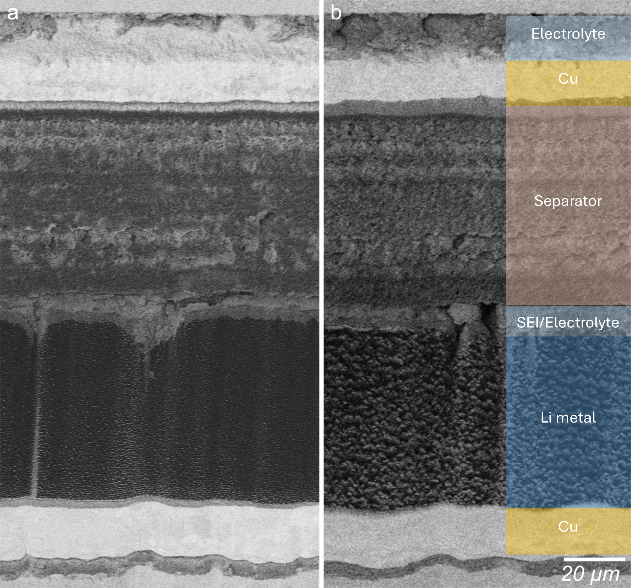
Figure 3.1:Wavelength-dependent LIPSS variation on coin cell ROI. Cryo-SEM backscatter electron (BSE) images of an uncycled (pristine) coin cell battery ablated with a) 515 nm and b) 1030 nm.
Because different materials will have different reflectivity for a given polarization, tuning the polarization varies both the LIPSS orientation and the cut face angle. Multiple beam paths and waveplates (integrated into laser control software) allow for the laser polarization to be instantaneously changed, which is important because LSFL (and sometimes HSFL) are typically perpendicular to the laser polarization, where the orientation of LIPSS can be rotated according to feature orientation or direction where features are least obscured by LIPSS. To clarify that importance, we studied the effect of polarization on wavelength-dependent LIPSS in identically prepared coin cells. Figure 3.2 (a) contains a region polished with p-polarized light (515 nm): the Li metal has polarization-perpendicular LSFL ripples, the LiH domians have polarization-perpendicular HSFL ripples, and the SEI/electrolyte have slight textural variation but no observable LIPSS. Figure 3.2 (b) shows a similar region from the same coin cell polished with s-polarized light (515 nm): the Li metal has generally vertical surface structures, but no ripples; the LiH deposit has HSFL with vertical ripples; and the SEI/electrolyte has no observable LIPSS. Figure 3.2 (c) and (d) are both taken from the same coin cell identically prepared to with the coin cell from Figure 3.2(a) and (b) and show a region with Li metal, SEI/electrolyte, and polymer separator. Figure 3.2 (c) was polished with p-polarized light (1030 nm) and shows LSFL only on the Li metal. Figure 3.2 (d) was polished with circularly polarized light (1030 nm) and shows LSFL as diagonal ripples only on the Li metal, but also shows slight variations in texture to the SEI/electrolyte and polymer separator.
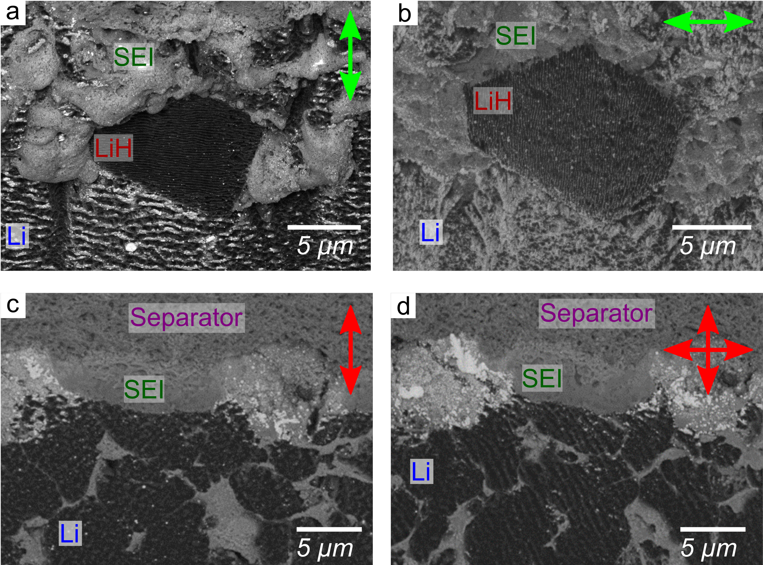
Figure 3.2:Effect of polarization on wavelength-dependent LIPSS in cycled coin cell ROI observed via Cryo-SEM BSE. A coin cell region with Li metal, SEI/electrolyte, and LiH domains polished with 515 nm a) p-polarization and b) s-polarization. A coin cell region with Li metal, SEI/electrolyte, and polymer separator polished with 1030 nm c) p-polarization and d) circular polarization.
While LIPSS are most often disadvantageous for the resolution of fine details, the ability to more cleanly differentiate different materials (e.g. Li metal from LiH domains; Li metal embedded in SEI) based on LIPSS presence and periodicity can be useful. For example, Figure 3.3 shows a sample polished at a 515 nm wavelength; within the SEI layer, it is easy to differentiate the Li domains (highlighted in blue) from voids and other textures embedded the SEI, which is extremely beneficial for segmentation purposes.
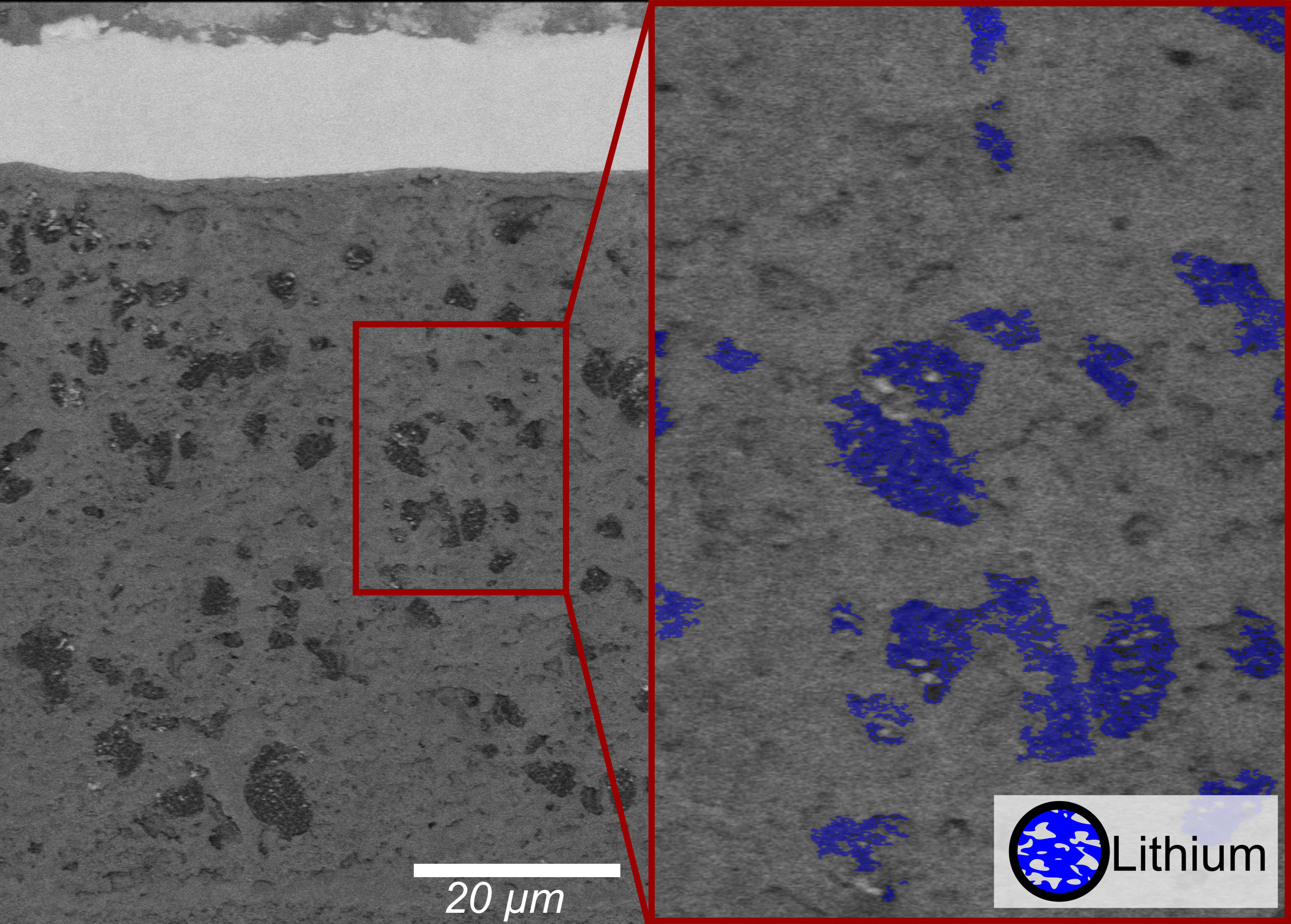
Figure 3.3:Cryo-SEM BSE images of a cycled coin cell battery with Li metal domains in SEI/electrolyte. The region highlighted in red on the right image is shown on the left. Li metal domains are highlighted with blue on the right.
Optimized Laser Cross-Section Workflow
A standard workflow was developed for preparing and imaging cross-sections on the coin cells to perform investigations of coin cells (i.e. with different components, cycling rates) to reveal microstructural, morphological, and composition information. After coin cells were loaded, a UPL bulk mill was used to remove the material of the targeted volume. To improve throughput, laser pattering was done in coarse mode with the longer wavelength at higher repetition rate, pulse energy, and larger pitch. This step resulted in significant redeposition of material onto the cross-section face, so an intermediate coarse polishing step was used to remove redeposition and clean the cross-section, using a smaller pattern pitch and reduced repetition rate. The UPL objective lens has a protective glass coverslip to prevent the lens from being coated by ablation debris, which is typically exchanged when changing specimen. In this case, due to the large volume of material removed and types of materials being removed, the protective coverslip would become coated after the bulk mill and coarse polish, significantly reducing the transmission of the 515 nm wavelength used for the final UPL step. The system chamber was vented and the coverslip was quickly exchanged. The sample remained at cryogenic temperatures, however a thin layer of frost could form while the cell was briefly exposed to air.
After replacing the protective coverslip on the UPL objective lens, the final laser step sought to optimize the cross-section quality and reveal smaller scale features using 515 nm in fine patterning mode. Lower repetition rates and pulse energy were favorable for most of the components in the stack (i.e., the polymer separator materials) to reduce the likelihood of damage and heat generation from parameters that result in higher average power that is outside of the athermal ablation regime. A summary of UPL parameters used for each step is shown in the table below. Pattern times could vary depending on thickness of the cell, requiring additional passes for a thicker cell.
Table 3.1:Cryo UPL Cut Parameters
| Process | Wavelength (nm) | Repetition Rate (kHz) | Pulse Energy (µJ) | Pattern Mode | Pattern Dimension (µm) | Pattern Pitch (µm) | Pattern Time (min) |
|---|---|---|---|---|---|---|---|
| Bulk Removal | 1030 | 20.0 | 40 | Coarse (1 ms/pixel) | 1200 x 900 | 10 x 10 | 03:36 |
| Coarse Polish | 1030 | 7.5 | 40 | Coarse (1 ms/pixel) | 1200 x 500 | 5 x 5 | 04:28 |
| Fine Polish | 515 | 1.0 | 10 | Fine, 5 pulses/pixel | 600 x 20 | 2 x 2 | 01:35 |
To optimize cut quality and reduce polishing time spent on sample areas outside of the ROI, the focus of the UPL was adjusted to the sample sub-surface. Rather than focusing at the sample surface, we moved the objective lens in towards the sample focusing just above the top of the battery stack. This significantly reduced polishing time, because it was unnecessary to fine polish the entire 250 μμm stainless-steel casing as shown in Figure 3.4. By reducing the area that needs to be fine polished, it is possible to mill multiphase materials using a reduced ablation threshold, repetition rates, pulse energy, and pitch, without increasing the polishing time. Additionally, in some cases, the quality of the cut face can be improved by changing the angle of incidence of the laser using the stage tilt (similar to performing an under or over-cut in a traditional Ga-ion FIB). To reduce redeposition on the ROI, it is possible to use variable tilts: coarse cut (stage tilt -5°, total tilt -31°), coarse polish (stage -6°, total -32°), and final fine polish (stage -8°, total -34°). We note that while these are the stages and conditions applied to coin cell batteries for our previous efforts, the laser ablation parameters could easily be tuned for other purposes; for example, cut-face quality could be sacrificed to further reduce patterning time or pitch parameters could be adjusted to improve characterization quality.

Figure 3.4:Cryo-SEM secondary electron (SE) images of a coin cell battery at each UPL patterning step, where blue highlighted regions show the UPL patterned region.
Plasma Focused Ion Beam Polishing
Following UPL ablation (coarse and intermediate), specific interfaces in the ROI be polished using the Xe+ PFIB. PFIB polishing can quickly remove the LIPSS, and provide a finer surface polish to reveal smaller length scale features that are not observable from UPL prepared cross-sections. On room temperature samples, this can be done easily with quick glancing angle polishes to remove a few hundred nm’s from the cross-section surface. PFIB milling was done in selected regions of interest within the laser prepared cross-section, where PFIB beam conditions varied based on the morphology of the battery stack (total thickness, specific regions of interest, and size of area requiring PFIB milling), but typically operating at 30 kV and 15 – 1000 nA. However, it was necessary to physically rotate the coin cell holder 180° so that the coin cell was facing the PFIB. Because the prototype system did not have a 360° rotation-capable cryo-stage, it was necessary to vent the system chamber and manually rotate the sample, which is less than ideal as it exposes the sample to humid air and risks the formation of ice on the sample. Fortunately, a sufficiently rapid execution of this technique allowed the sample to be rotated and start chamber pumping in less than a minute. Thus, while a layer of ice did form over the cross-section during rotation, the electrolyte remained frozen and the crucial interfaces were preserved. Conveniently, it is also very easy to remove the ice layer via 30 kV PFIB, without impeding subsequent PFIB polishing in any discernable way. Although this step will be unnecessary in a 360° rotation-capable cryo-stage, it may still be useful as a method for finding regions to target for cryo-liftout and TEM preparation.
Figure 3.5 (a) and (b) show a laser polished area and ROI, which was then PFIB-polished, shown in Figure 3.5 (c) and (d). Note that the region in Figure 3.5 (b) is a higher magnification image from the region in the red box marked in Figure 3.5 (a). This cross-section was obtained in coin cell where failure occurred in the polymer separator, similar to that discussed in previous work Merrill et al., 2023. Due to this failure and Li metal morphology observed in the laser cut region, this area was polished with PFIB, which is shown in Figure 3.5 (c)and (d). Figure 3.5 (d) contains a higher magnification image of the region marked with a red box in Figure 3.5 (c). All LIPSS were removed from the surface after PFIB polishing, which revealed small Li metal domains that were not evident in the laser cut area. In addition, features and Li domains in the SEI/electrolyte which were not observed in the laser cut area are prominent in the PFIB polished region, which is particularly evident in Figure 3.5 (d).

Figure 3.5:Cryo-SEM BSE images of a PFIB-polished coin cell battery with Li metal domains in SEI/electrolyte. a) UPL prepared cross-section and b) higher magnification image of region marked with a red box in a). c) Image after PFIB polish on UPL prepared cross-section from a) and b), where d) shows a higher magnification image of region marked with a red box in c).
- Merrill, L. C., Gannon, R. N., Jungjohann, K. L., Randolph, S. J., Goriparti, S., Zavadil, K. R., Johnson, D. C., & Harrison, K. L. (2023). Evaluation of Lithium Metal Anode Volumetric Expansion through Laser Plasma Focused Ion Beam Cross-Sectional Imaging. Journal of The Electrochemical Society, 170(8), 080527. 10.1149/1945-7111/acf162

