Evaluating the Transfer of Information in Phase Retrieval STEM Techniques
Analytical Framework for Contrast Transfer Functions in STEM Measurements
STEM Image Formation
The electron wavefunction of a converged electron probe exiting a thin sample is given by Hammel & Rose, 1995:
where ψ is the converged electron probe at the object plane, centered at position and defined across arbitrary positions in the object plane, is the complex-valued transmission function of the sample phase, .
The transmitted electron wavefunction is then propagated to the far-field detector plane given by:
where is the Fourier operator which transforms positions in the object plane, , to positions in the detector plane, .
While the electron wavefunction at the detector plane is complex-valued, physical detectors can only record its probability density, given by:
where we have omitted the incoherent integrals resulting from the temporal and spatial partial coherence of the electron source Hammel & Rose, 1995.
Finally, the intensity recorded on a specific detector segment or pixel is given by:
where is the detector response function for the jth segment or pixel.
In general, the relationship between (2.3) and the sample phase is non-linear. Weak-phase objects only scatter the incoming illumination weakly, and can thus be well approximated using the leading terms of the Taylor expansion, known as the weak phase object approximation (WPOA),
In this case, the image formation theory described above becomes linear, and the image contrast is proportional to the sample phase. This is most commonly expressed in terms of the intensity Fourier transform,
as a function of spatial frequency, . Note that we use to denote the spatial frequency corresponding to a specific scan position. This is different from which denotes position in the detector plane. The intensity Fourier transform becomes
where is the complex-valued contrast transfer function (CTF), which is sample-independent and depends on the properties of the imaging system, such as the incoming illumination aperture and aberrations, the detector geometry, and the reconstruction method.
Contrast Transfer Functions
For STEM measurements, the complex-valued CTF function takes the form Hammel & Rose, 1995:
where is the probe-forming aperture and is the aberration surface. is a top-hat function normalized such that , and
where , , λ is the electron wavelength, and are the radial and azimuthal orders of the aberration coefficients , and is the aberration axis of non-isotropic coefficients.
Equation (2.8) can be expressed more compactly using symmetric and asymmetric weighted cross-correlations of the complex-valued wavefunction with the detector function:
where denotes cross-correlation and , denote the real and imaginary parts of complex-valued expressions respectively.
For a pixelated detector sampled at Nyquist, , the integrand of (2.8) reduces to:
which is known as the spatial-frequency dependent aperture-overlap function and encodes the phase interference between the first order diffracted beams and the direct beam Yang et al., 2016.
Aperture Autocorrelation
It is instructive to explore (2.8) - (2.11) for the ideal case of no aberrations, , and a circular probe-forming aperture with convergence semiangle defined by:
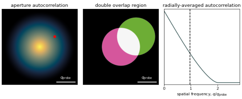
In this case (2.10) reduces to the aperture auto-correlation function:
Intuitively, (2.13) can be interpreted as the “double overlap” area between the aperture and a shifted aperture centered at . Figure 2.1 illustrates this interactively, as well as plot the radially-averaged aperture autocorrelation function.
Notice (2.13) has support up to and is zero beyond that. With the exception of iterative ptychography, which we explore in-depth in Iterative Ptychography with a Pixelated Detector, all STEM phase-retrieval methods are limited by the aperture autocorrelation function.
Aberration Surface
Similarly, for axial illumination, , (2.8) reduces to the HRTEM CTF:
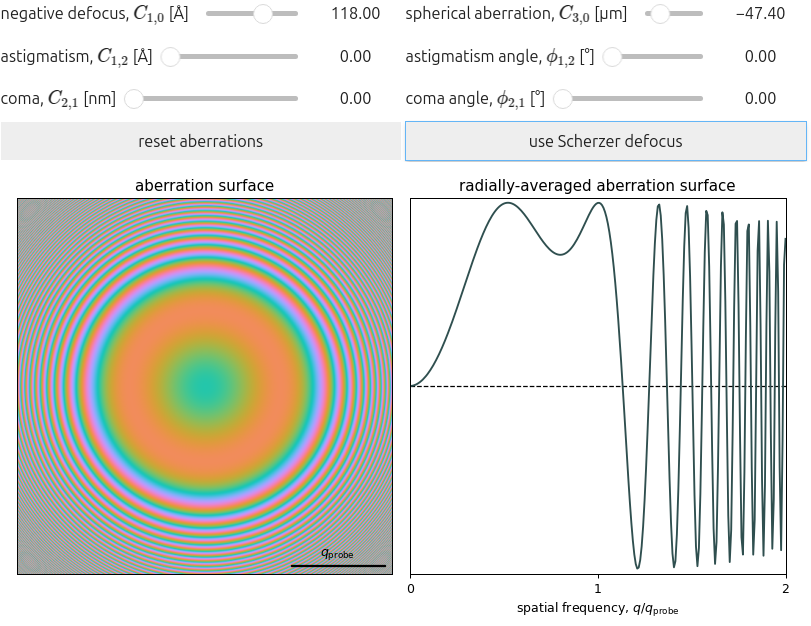
Figure 2.2 plots (2.14) for common low-order aberration coefficients, illustrating the effect these have on the imaging wavefront. For TEM, the resolution achievable is limited by the first contrast reversal, which is pushed to lower spatial frequency with increasing spherical aberration. Figure 2.2 therefore also has the functionality to balance the spherical aberration, and optimize contrast transfer, using Scherzer defocus:
where denotes the sign of a real number.
In STEM, on the other hand, the achievable resolution is often limited by the size of the probe used to scan the sample. Since a larger probe-forming aperture yields a smaller probe, the aperture should usually be as large as practically possible while limiting probe aberrations. Figure 2.2 visualizes how low-order aberrations impact the aberration surface, providing a tool to estimate how large the probe forming aperture may be to ensure a maximum of phase shift.
- Hammel, M., & Rose, H. (1995). Optimum rotationally symmetric detector configurations for phase-contrast imaging in scanning transmission electron microscopy. Ultramicroscopy, 58(3–4), 403–415. 10.1016/0304-3991(95)00007-n
- Yang, H., Ercius, P., Nellist, P. D., & Ophus, C. (2016). Enhanced phase contrast transfer using ptychography combined with a pre-specimen phase plate in a scanning transmission electron microscope. Ultramicroscopy, 171, 117–125. 10.1016/j.ultramic.2016.09.002


