Evaluating the Transfer of Information in Phase Retrieval STEM Techniques
Integrated Center of Mass Imaging with a Pixelated Detector
One of the unique features of STEM over TEM phase retrieval techniques is that signal subtraction is possible, and as we will see desirable in some configurations. For a complicated detector geometry
for real (and possibly negative) coefficients , the linearity of (2.8) suggests that the CTF for a complicated geometry follows the relation:
Center of Mass Imaging
One popular detector geometry utilizing signal subtraction is differential phase contrast (DPC), or more generally center-of-mass (COM) imaging Chapman et al., 1990. This utilizes the fact that the gradient of the sample phase is proportional to the shift in the center of mass of the observed diffraction intensities Dekkers & De Lang, 1974. The COM may be estimated using either pixelated or segmented detectors, e.g. by subtracting the intensity in opposing detector segments. Both methods of estimating the COM signal enable us to recover the phase modulation applied to the incoming illumination by long range magnetic and electric fields Chapman et al., 1978Lohr et al., 2012Shibata et al., 2015, and the local electric field surrounding atomic nuclei Shibata et al., 2012Nellist, 2012.
Formally, the detector function used in COM imaging is a vector proportional to the detector plane position
where and are unit-vectors on the detector plane along the x- and y-directions respectively. Inserting the COM detector components in (2.10), we obtain the following CTFs for each cartesian direction Lazić & Bosch, 2017Oster & Kohl, 2023:
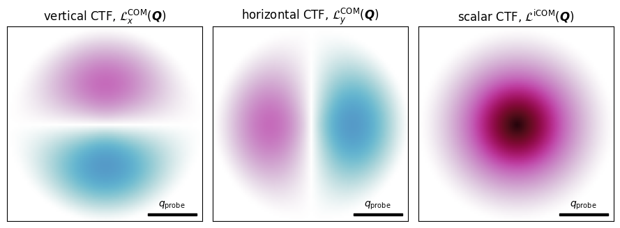
Figure 3.1:Center of mass imaging component CTFs, and how they combine to give the scalar iCOM CTF, for an in-focus probe.
The first two panels of Figure 3.1 plot the COM CTFs for the vertical and horizontal directions for the ideal case of no probe aberrations. These also exhibit support up to , consistent with the aperture autocorrelation function shown in Figure 2.1.
Integrated Center of Mass Imaging
Since the COM signal is proportional to the gradient of the sample phase, the signal may be numerically integrated to retrieve the projected sample phase. This yields the integrated differential phase contrast (iDPC), or more generally iCOM, signal Lazić et al., 2016Bosch et al., 2016.
Following (3.2), the vectorial CTF in (3.4) can be combined to form a scalar CTF using the usual Fourier-integration method of obtaining the iCOM signal Lazić & Bosch, 2017:
This is shown in the right panel of Figure 3.1, and note that this reduces to the much simpler expression for the autocorrelation of the complex-valued wavefunction:
Effect of Probe Aberrations on iCOM CTF
Figure 3.2 plots (3.6) for low-order isotropic aberration coefficients, namely and . Note that the CTF degrades quickly with increasing aberrations, hence iCOM is traditionally performed in-focus. Additionally, note that the Scherzer defocus is not in-fact optimal for a specific chromatic aberration, since the CTF does not exhibit the same zero-crossings as the HRTEM CTF.
The right-most panel utilizes the linearity of the WPOA to convolve the resulting CTF with three sample potentials at various length-scales: i) a thin strontium titanate (STO) sample, ii) a metal-organic framework sample, and iii) an apoferritin protein sample. Note that at large defocuses, the CTF can exhibit contrast reversals.
Figure 3.2:Effect of various probe aberrations on the CTF for iCOM imaging with a pixelated detector. The resulting CTF is shown on the left panel, with its radial average in the middle panel, and its effect on example weak phase objects on the right panel.
Finally, it is interesting to note that analytical iCOM CTF suggests that the mean value of the reconstructed phase, given by the direct-component (DC) frequency, is recovered exactly. This is incorrect, since only off-axis holographic techniques can recover the absolute phase of a sample, and highlights the main limitation of CTF analysis – namely that it completely neglects finite electron fluence and Poisson-limited detector measurements. We remedy this point in Spectral Signal to Noise where we introduce the spectral signal-to-noise (SSNR) statistical framework.
- Chapman, J. N., McFadyen, I. R., & McVitie, S. (1990). Modified differential phase contrast Lorentz microscopy for improved imaging of magnetic structures. IEEE Transactions on Magnetics, 26(5), 1506–1511. 10.1109/20.104427
- Dekkers, N. H., & De Lang, H. (1974). Differential phase contrast in a STEM. Optik, 41(4), 452–456.
- Chapman, J. N., Batson, P. E., Waddell, E. M., & Ferrier, R. P. (1978). The direct determination of magnetic domain wall profiles by differential phase contrast electron microscopy. Ultramicroscopy, 3, 203–214. 10.1016/S0304-3991(78)80027-8
- Lohr, M., Schregle, R., Jetter, M., Wächter, C., Wunderer, T., Scholz, F., & Zweck, J. (2012). Differential phase contrast 2.0—Opening new “fields” for an established technique. Ultramicroscopy, 117, 7–14. 10.1016/j.ultramic.2012.03.020
- Shibata, N., Findlay, S. D., Sasaki, H., Matsumoto, T., Sawada, H., Kohno, Y., Otomo, S., Minato, R., & Ikuhara, Y. (2015). Imaging of built-in electric field at a p-n junction by scanning transmission electron microscopy. Scientific Reports, 5(1). 10.1038/srep10040
- Shibata, N., Findlay, S. D., Kohno, Y., Sawada, H., Kondo, Y., & Ikuhara, Y. (2012). Differential phase-contrast microscopy at atomic resolution. Nature Physics, 8(8), 611–615. 10.1038/nphys2337
- Nellist, P. D. (2012). Atomic resolution comes into phase. Nature Physics, 8(8), 586–587. 10.1038/nphys2357
- Lazić, I., & Bosch, E. G. T. (2017). Analytical Review of Direct Stem Imaging Techniques for Thin Samples. In Advances in Imaging and Electron Physics (pp. 75–184). Elsevier. 10.1016/bs.aiep.2017.01.006
- Oster, A., & Kohl, H. (2023). Optimized detector configurations for the reconstruction of phase-contrast images in scanning transmission electron microscopy. Ultramicroscopy, 246, 113670. 10.1016/j.ultramic.2022.113670
- Lazić, I., Bosch, E. G. T., & Lazar, S. (2016). Phase contrast STEM for thin samples: Integrated differential phase contrast. Ultramicroscopy, 160, 265–280. 10.1016/j.ultramic.2015.10.011
- Bosch, E. G. T., Lazic, I., & Lazar, S. (2016). Integrated Differential Phase Contrast (iDPC) STEM: A New Atomic Resolution STEM Technique To Image All Elements Across the Periodic Table. Microscopy and Microanalysis, 22(S3), 306–307. 10.1017/s1431927616002385

