Evaluating the Transfer of Information in Phase Retrieval STEM Techniques
Direct Ptychography with a Pixelated Detector
Direct ptychographic methods can be viewed as deconvolution techniques. Specifically, they use the interference information encoded in the overlap between the diffracted beams and the direct beam to extract the sample phase. Intuitively, for a specific wavevector , the convolutional effect of the probe can be modeled to estimate the expected phase modulation in the observed diffraction patterns, and any additional phase modulation may thus be attributed to the sample.
Different direct ptychographic techniques perform this deconvolution differently:
- “traditional” SSB Pennycook et al., 2015, sums the phase information in one of the “double-overlap” regions to obtain an average estimate of the sample phase
- This only works in the absence of probe aberrations and will be omitted in this work.
- “phase-compensated” SSB Yang et al., 2016, uses (2.11) to perform multiplicative deconvolution, thus “flattening” the phase in the “double” and “triple” overlap regions before summing to obtain a more robust estimate of the sample phase.
- OBF Ooe et al., 2021, uses the same multiplicative deconvolution idea, albeit using a signal-to-noise optimizing normalization weights.
- This is traditionally used with segmented detectors and we explore it further in Direct Ptychography with a Segmented Detector.
- WDD Yang et al., 2016, uses Wiener deconvolution to isolate the sample phase, after first casting the expected phase modulation in terms of the shifted Wigner distribution function.
- tcBF Yu et al., 2024, does not traditionally use deconvolution but we introduce a novel algorithm leveraging multiplicative deconvolution in Upsampled Direct Ptychography.
Phase Compensated SSB CTF
In contrast to the detector response functions we have investigated so far, direct ptychography can utilize all the phase information in the complex-valued aperture-overlap function (2.11). This suggests that its CTF is instead given by summing the non-zero regions of (2.11), which yields:
While the absolute value inside the integrand precludes a cleaner expression using correlation functions, which rely on linearity, (4.1) can be parallelized efficiently across spatial frequencies, .
For completeness, we note in passing that for the ideal case of no probe aberrations, , (4.1) reduces to the well-known geometric “double-minus-triple overlap” expression given by Yang et al., 2015:
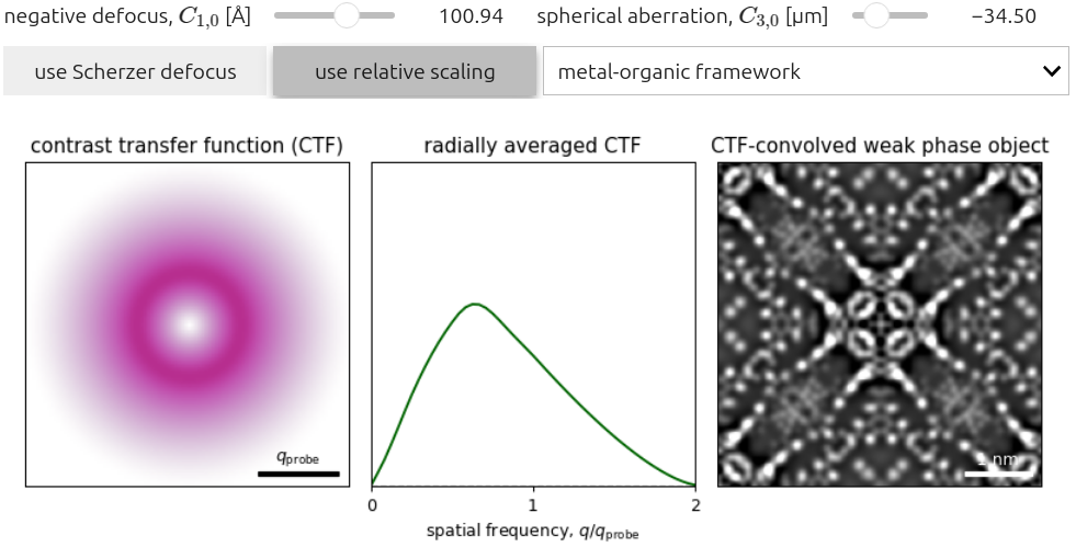
Figure 4.1 plots (4.1) for low-order isotropic aberration coefficients, namely and . We note the following:
- The CTF tends to zero for and , peaking in between.
- The CTF is purely positive, leading to no contrast reversals with aberrations (and by extension thickness).
- Similar to iCOM, the Scherzer defocus condition is suboptimal in the presence of spherical aberration, since the SSB CTF exhibits no zero-crossings.
- Pennycook, T. J., Lupini, A. R., Yang, H., Murfitt, M. F., Jones, L., & Nellist, P. D. (2015). Efficient phase contrast imaging in STEM using a pixelated detector. Part 1: Experimental demonstration at atomic resolution. Ultramicroscopy, 151, 160–167. 10.1016/j.ultramic.2014.09.013
- Yang, H., Ercius, P., Nellist, P. D., & Ophus, C. (2016). Enhanced phase contrast transfer using ptychography combined with a pre-specimen phase plate in a scanning transmission electron microscope. Ultramicroscopy, 171, 117–125. 10.1016/j.ultramic.2016.09.002
- Ooe, K., Seki, T., Ikuhara, Y., & Shibata, N. (2021). Ultra-high contrast STEM imaging for segmented/pixelated detectors by maximizing the signal-to-noise ratio. Ultramicroscopy, 220, 113133. 10.1016/j.ultramic.2020.113133
- Yu, Y., Spoth, K. A., Colletta, M., Nguyen, K. X., Zeltmann, S. E., Zhang, X. S., Paraan, M., Kopylov, M., Dubbeldam, C., Serwas, D., Siems, H., Muller, D. A., & Kourkoutis, L. F. (2024). Dose-Efficient Cryo-Electron Microscopy for Thick Samples using Tilt-Corrected Scanning Transmission Electron Microscopy, Demonstrated on Cells and Single Particles. 10.1101/2024.04.22.590491
- Yang, H., Pennycook, T. J., & Nellist, P. D. (2015). Efficient phase contrast imaging in STEM using a pixelated detector. Part II: Optimisation of imaging conditions. Ultramicroscopy, 151, 232–239. 10.1016/j.ultramic.2014.10.013


