Evaluating the Transfer of Information in Phase Retrieval STEM Techniques
Integrated Center of Mass Imaging with a Segmented Detector
One of the simplest ways to use the signal from a classical four-segmented detector is estimating the COM of the BF disk by subtracting opposing detector segments. It was shown over a decade ago that this enables imaging of single atomic columns Shibata et al., 2012. However, segmented detectors of other geometries may be realized as well, and the CTF framework lends itself well to investigating the information transfer dependency on the detector geometry.
Analytical Segmented COM CTF
In Integrated Center of Mass Imaging with a Pixelated Detector, we saw that the analytical CTF for iCOM with a pixelated detector is the autocorrelation of the complex probe, since the pixelated detector function covers every pixel in the detector as seen in (3.3). For a segmented detector given by (7.1) the combined vectorial detector function is given by:
with the analytical segmented COM CTFs obtained by Lazić & Bosch, 2017:
Detector Segmentation iCOM CTF
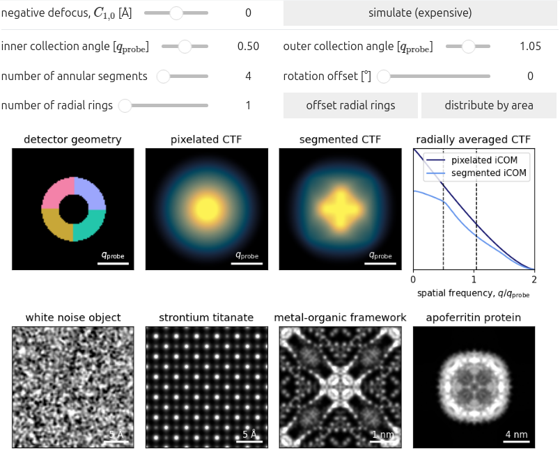
The iCOM CTF is then obtained from (8.2) using the same Fourier-integration technique given by (3.5). Figure 8.1 plots the iCOM CTF for various detector geometries, highlighting how the symmetry of the detector is reflected in the symmetry of the two-dimensional CTF.
We note the following:
- As the number of annular and radial segments increases, the iCOM CTF approaches that of the pixelated detector.
- Similarly to pixelated iCOM, the CTF degrades quickly with increasing defocus. The effect is even more pronounced with large, few detector elements.
- Since the CTF relies on the center of mass of detector segment , the outer collection angle of an annular detector should match the semi-convergence angle, α, for the COM approximation to be accurate.
- An outer collection angle results in over-estimation of the COM signal, and thus produces a CTF above unity.
- This effect may be somewhat remedied by introducing radial rings which allows the detector to resolve the COM signal radially in addition to annularly.
- For detectors with few annular segments, the 2D CTF is anisotropic, resulting in non-round atoms when convolved with the STO WPO.
- The rotational-offset of the annular segments is reflected in the 2D CTF orientation.
- Note this effect is obfuscated in the commonly-presented 1D radial averages.
- Offsetting half of the ring’s segments by half of their annular span range (e.g. for four segments spanning each) further improves annular resolution, yielding a more isotropic CTF.
- Shibata, N., Findlay, S. D., Kohno, Y., Sawada, H., Kondo, Y., & Ikuhara, Y. (2012). Differential phase-contrast microscopy at atomic resolution. Nature Physics, 8(8), 611–615. 10.1038/nphys2337
- Lazić, I., & Bosch, E. G. T. (2017). Analytical Review of Direct Stem Imaging Techniques for Thin Samples. In Advances in Imaging and Electron Physics (pp. 75–184). Elsevier. 10.1016/bs.aiep.2017.01.006


